The present PSTN telephone line transmits voice signal between 0 - 3000hz which supports modem data transmission at typically 2400 hz or baud.
Baud refers to cycles of wave form transmitted per second. It was equivalent to the number of bits per second transmitted when modems were runinig for 300 bps to 1200 bps. The classic explanation of modems is that they convert digital bits and bytes to a series of audio tones by MODULATING a carrier. And at the receiving end, they DEMODULATE this carrier by detecting the tones and converting them back into digital bits - one state change represented one bit.
Today's modems encode data to allow each change in state in the audio waveform to represent a variable number of data bits. This is done by varying two waveform variables - Amplitude and Phase that can be controlled and using them to symbolically represent data. There are three modulation methods available: Amplitude, Frequency and Phase. As frequency range is limited by phone line capacity and phase shift keying modulation requires a stable frequency, frequency modulation has largely been abandoned. The audio carrier is essentially a sinusoidal oscillation that goes through a 360 degree cycle with each oscillation. We can detect fairly small phase differences between sinusoidal waveforms. And so phase-shift keying or PSK became a preferred modulation technique.
Using these two variables, phase and amplitude, we can use the various state combinations to represent binary data. In this way, we can transmit a number of binary bits via a single symbol. Let's look at a simple example:
 Figure 1
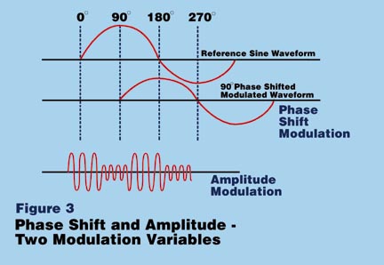
Two modems, in the process of the initial handshake, can synchronize internal reference generators to establish a reference waveform. They can then transmit phase modulated waveforms between them. By comparing the received modulated waveform to the reference waveform, they can detect phase angle differences. We can use these phase angle differences to represent data.
 Figure 2
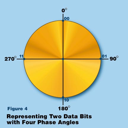
Figure 2 shows phase angles of 0 degrees, 90 degrees, 180 degrees, and 270 degrees. We can arbitrarily use these phase states to represent binary data as follows:
|
| | 0 degrees | 00 |
| 90 degrees | 01 |
| 180 degrees | 10 |
| 270 degrees | 11 |
Note that by transmitting a SINGLE symbol in one of FOUR states, we can actually pass TWO bits of binary data. This is rather magnified by using finer divisions of phase-state:
| | 0 degrees | 000 |
| 45 degrees | 001 |
| 90 degrees | 010 |
| 135 degrees | 011 |
| 180 degrees | 100 |
| 225 degrees | 101 |
| 270 degrees | 110 |
| 315 degrees | 111 |
We now have 8 phase states, but we also now represent THREE binary bits via the transmission of a SINGLE phase-state symbol. A single change in phase of the sinusoidal waveform allows us to transmit three bits of data.
The other variable we can easily manipulate is the AMPLITUDE of the waveform. During the initial connection sequence between modems the two modems have to agree that a signal THIS loud is a significant amplitude level, while a signal THAT loud would be recognized as a DIFFERENT amplitude level.
The addition of amplitude allows us to increase the amount of data transmitted.
| Amplitude | Phase | Binary Data |
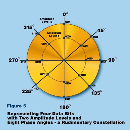
| Level 1 | 0 degrees | 0000 |
| Level 1 | 45 degrees | 0001 |
| Level 1 | 90 degrees | 0010 |
| Level 1 | 135 degrees | 0011 |
| Level 1 | 180 degrees | 0100 |
| Level 1 | 225 degrees | 0101 |
| Level 1 | 270 degrees | 0110 |
| Level 1 | 315 degrees | 0111 |
| Level 2 | 0 degrees | 1000 |
| Level 2 | 45 degrees | 1001 |
| Level 2 | 90 degrees | 1010 |
| Level 2 | 135 degrees | 1011 |
| Level 2 | 180 degrees | 1100 |
| Level 2 | 225 degrees | 1101 |
| Level 2 | 270 degrees | 1110 |
| Level 2 | 315 degrees | 1111 |
In this example, using two amplitude variations, and our 8 phase states, we can transmit 4 bits of data for each unique combination - let's call these quantization levels. For each single and instantaneous change in amplitude and phase, we can transmit FOUR bits of data. Figure 5 shows a very basic CONSTELLATION using two levels of amplitude and eight phase angle states to represent four data bits with a single symbol transmission.
 Figure 3
If we add another amplitude level, we get five bits per symbol. And if we continue to add finer phase angles, and finer amplitude levels, we will be able to code more bits into a waveform. However,There is a up-limit as to how fine we can go. the finer division of phase shifts and amplitude levels will become increasingly difficult to differentiate from each other on the receiving end. They also are interfered by the analog line environment which has its own inductance, capacitance, noise, etc.
The telephone system has already been converted to digital technology. Almost all connections between central switching offices themselves and ISPs are done digitally and increasingly over fiber. Really, the only analog portion of the system in most areas is the last link from central office switch to the customer's home.
The reason that 56 kbps speeds are possible is not so much that the data is being transmitted in digital form between the ISP and the central switching office. It is that in doing so we have ELIMINATED SEVERAL DIGITAL/ANALOG and ANALOG/DIGITAL conversions. These conversions tend to introduce interferences into the signals.
It is much easier to convert a digital signal to a fairly precise analog waveform for transmission, than it is to analyze a received analog waveform, detect small variations in phase and amplitude, and create a digital signal from that information. In going from the switch to the local loop, DOWN to the customer, we are still performing a Digital to Analog conversion. We can convert digital signals to an analog waveform with great precision. But on the UPSTREAM side, at the telephone switch we are converting an incoming analog waveform to digital data - much more difficult to do accurately. This is why with the new 56 kbps technology, we can achieve data rates of 56 kbps DOWNSTREAM to the customer. But we are still limited to 33.6 kbps UPSTREAM from the customer to the ISP.
 An illustration of modem speed


